Tools

How to check fuel pressure with a Petrol Fuel Injection Pressure Test Kit

BERGEN 11 Pce Petrol Fuel Injection Pressure Test Kit 0-145psiGENERAL INFORMATION

Because fuel systems and access points are so varied, it is impractical to list all of the applications. Always refer to a reliable shop manual, or the car manufacturer for the recommended test procedure and access points.

There are two basic types of fuel injection systems.

Port Fuel Injection (PFI) uses separate injectors to supply the fuel to each cylinder.

Throttle Body Injection (TBI) injects fuel from a position above the throttle plate on the intake manifold. On both systems there is a supply side, which brings fuel to the injectors, and a return side which brings unused fuel back to the tank.

Basically, there are three ways to check fuel pressure.

First, many domestic cars with PFI are equipped with a special test port.

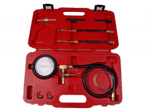
Simply connect the proper adaptor to the gauge assembly, thread the adaptor to the test port, and run the test.

Second is an end of hose connection.

Some older PFI systems have a flexible hose connection at the cold start injector. Connect our single barb fitting with a hose clamp to run the test. Also, some systems have fuel bolt or banjo type fittings as an access point

Third is in-line connecting.

This means installing the proper adaptor(s) in series with the fuel line .

Unless a Schrader-type test port is available, most manufacturers require that you relieve the fuel pressure before entering or leaving the system. To relieve the pressure, it may be necessary to remove the fuel pump connector, relay, or fuse. Some models may have two fuel pumps – make sure both are disabled.

After the pump(s) are disabled, run the engine until it stalls, then try to restart it for five to ten seconds. The system is now ready for testing. Once the proper adaptors and gauge are in place, reactivate the fuel pump and run tests. When finished testing, repeat above procedure before removing tester.

BASIC DIAGNOSIS

Fuel injected engines require precise fuel pressure as well as adequate volume. Without the correct pressure and volume, performance and fuel economy can suffer.

Always consult the correct repair manual for accurate specifications.

When running tests, it may help to picture the fuel system as a circle. Fuel is pumped from the tank to the fuel regulator and injectors, and the unused fuel is then returned to the tank. The fuel regulator serves as a divider between the supply side and the return side. Lower than recommended pressure usually indicates a problem on the supply side of the circle. Likely causes would include a damaged or restricted fuel line, clogged fuel filter, defective fuel pump or regulator, or improper tank ventilation. Higher than normal pressure usually indicates a problem on the return side of the circle. Likely causes are a damaged or restricted fuel line, poor venting of the tank, or a defective fuel regulator.

You may be able to pinpoint problem areas on the return side by resetting. For example – by removing the return line near the fuel regulator and putting the fuel line into a proper container, a retest that still shows a high reading would indicate a faulty regulator. If the reading would drop into the normal range, you know that problem is further down the return line or the tank. Again, always consult the manufacturer of the vehicle, or a good repair manual for specific trouble-shooting procedures. When testing is completed, make sure the fuel line is reassembled correctly. Replace any o-rings or washers, and follow the manufacturer’s recommendations for proper torque on any bolts or connections. Check the entire system thoroughly for any leaks.

Following are some typical test procedures for different models.

FUEL PRESSURE TESTS FOR GENERAL MOTORS (TYPICAL)

CAUTION: Fuel system test begins with checking fuel injection system pressure. High fuel pressure may be present in fuel lines and components. Relieve fuel pressure before disconnecting any fuel system components.

FUEL PRESSURE CHECK FOR TBI

1. Disconnect negative battery cable. Remove fuel filler cap. Since these TBI units contain an internal bleed-down feature, after a short time, system fuel pressure should dissipate.
2. Remove air cleaner and plug thermal vacuum port on throttle body. When removing fuel line, always use 2 wrenches. Install Fuel Pressure Gauge and Adaptor in fuel system between steel line and flexible hose. CAUTION: DO NOT pinch off fuel return line completely. DO NOT exceed pressure build-up of more than 13 psi. as regulator may be damaged.
3. Start engine and observe fuel pressure reading. Fuel pressure should read 9-13 psi. (if fuel pressure is okay, proceed to step 4). If fuel pressure is low, gradually pinch off fuel return line to fuel tank. If pressure remains low, check and/or replace fuel filter or fuel pump. If pressure increases to greater than 13 psi, replace fuel pressure regulator.
4. Allow fuel pressure to dissipate. Remove pressure gauge and reconnect fuel line. Start engine and watch for fuel system leaks.

FUEL PRESSURE CHECK OF PFI

1. Disconnect fuel pump at rear body connector (electrical). Start engine and run engine until it stalls. Crank starter for 3 seconds to remove remaining fuel from fuel lines. Reconnect rear body connector.
2. Connect Fuel Pressure Gauge to fuel pressure fitting on fuel rail.
3. Reconnect fuel pump.
4. With gauge installed at fuel rail connector, turn ignition on. With ignition on and engine off, pressure should read within specifications.
5. Start engine. Pressure should drop 3-10 psi.

FUEL PRESSURE TESTS FOR FORD (TYPICAL)

CAUTION: High fuel pressure may be present in fuel lines and component parts. Relieve pressure before attempting to open system for testing or component replacement. DO NOT allow fuel to run onto engine or electrical parts or allow an open flame in area while testing fuel system components.

FUEL PRESSURE CHECK FOR PFI

1. On 2.2L & 2.2L Turbo models, relieve fuel line pressure by disconnecting fuel pump relay and starting engine. After engine stalls, turn ignition off. Reconnect fuel pump relay.
2. On all other models, remove fuel tank cap. Using Fuel Pressure Gauge, release pressure from system at pressure relief valve (Schrader valve) on fuel injection manifold rail.
3. The fuel pump may be activated by grounding the fuel pump lead at the SELF-TEST connector. Use a jumper lead and ground the “FP” terminal with ignition on. This activates the fuel pump. CAUTION: Inspect fuel system for leaks or damage before testing fuel pump.

FUEL PRESSURE TEST FOR TBI

1. Disconnect wiring at inertia switch. Inertia switch is located behind trim panel in right rear side of cargo area on Sable and Taurus station wagons and behind trim panel on left side of trunk on all other models. Crank engine for at least 15 seconds to reduce system fuel pressure.
2. Disconnect fuel supply line at throttle body. Install in-Line Adaptor and fuel Pressure gauge at fuel filter. Reconnect inertia switch and start engine. Check fuel pressure at idle and when accelerating engine. Pressure should remain stable through entire period of acceleration.
3. If gauge readings are correct, disconnect inertia switch. Crank engine for 15 seconds to reduce fuel pressure. Remove gauge and in-line adaptor. Install original fuel line and connect inertia switch. Start engine and check for fuel leaks.

FUEL PRESSURE TESTS FOR CHRYSLER (TYPICAL)CAUTION:

High fuel pressure may be present in fuel lines and component parts. Relieve pressure before attempting to open system for testing or component replacement. DO NOT allow fuel to run onto engine or electrical parts while testing fuel system components.

FUEL PRESSURE RELEASEBERGEN 11 Pce Petrol Fuel Injection Pressure Test Kit 0-145psi

1. Fuel Pressure must be fully released before opening fuel system or removing any fuel carrying components. To release pressure in tank, open fuel tank cap slowly.
2. To release remaining pressure in system, disconnect fuel pump connector (electrical) in boot and crank engine.

TBI FUEL PUMP TEST

1. Release fuel pressure. Disconnect 5/16″ fuel supply hose. Connect fuel system pressure Gauge between fuel supply hose and engine fuel line.
2. Turn ignition on. Activate fuel pump. If fuel pump pressure is at specification, fuel system is functioning properly.
3. If fuel pressure is not to specification, record pressure. Install fuel pressure gauge in fuel supply line at rear of vehicle between fuel tank and fuel filter.
4. Activate fuel pump. Record pressure reading. If fuel pressure is 5 psi higher than the first pressure reading, replace fuel filter.
5. If no change in pressure reading is observed, gently squeeze fuel return hose. If fuel pressure increases, replace fuel pressure regulator. If no change in fuel pressure is observed, problem is plugged fuel pump filter sock or defective fuel pump.
6. If fuel pressure is more than specification, remove fuel return hose at rear of vehicle. Connect an extension hose to return hose. Place hose in an approved container with at least a 2 gallon capacity.
7. Activate fuel pump. If fuel pressure is now within specification, check in-tank return fuel hose for kinking. Replace fuel tank assembly if in-tank reservoir check valve or aspirator jet is plugged.
8. If fuel pressure is still more than specification, remove fuel return hose from throttle body. Connect a substitute hose to throttle body return nipple. Place other end of hose in an approved container.
9. Activate fuel pump. If fuel pressure is at specification, check for a restricted fuel return line between throttle body and fuel tank. If no change was observed, replace fuel pressure regulator. NOTE: Perform fuel pump test with fuel tank at least half full. Before disconnecting a fuel line during testing, repeat fuel pressure release procedure.

PFI FUEL PUMP TEST

1. Release fuel pressure. Remove cap from service valve on fuel rail. Connect fuel system pressure Gauge to service valve.
3. If fuel pressure is not to specification, record pressure and remove gauge. Activate pump. Ensure no fuel leaks from service valve. Install cap on service valve.
4. If fuel pressure is not to specification, install pressure gauge in fuel supply line between fuel tank and fuel filter at rear of vehicle. Activate fuel pump.
5. Record pressure reading. If fuel pressure is 5 psi higher than the first pressure reading, replace fuel filter. If no change in pressure reading is observed, gently squeeze fuel return hose.
6. If fuel pressure increases, replace fuel pressure regulator. If no change in fuel pressure is observed, problem is plugged fuel pump filter sock or defective fuel pump.
7. If fuel pressure is more than specification, remove fuel return hose at rear of vehicle. Connect an extension hose to return hose. Place hose in an approved container with at least a 2 gallon capacity.
8. Activate fuel pump. If fuel pressure is now within specification, check in-tank return fuel hose for kinking. Replace fuel tank assembly if in-tank reservoir check valve or aspirator jet is plugged.
9. If fuel pressure is still more than specification, remove fuel return hose from pressure regulator. Connect a substitute hose to fuel pressure regulator. Place other end of hose in an approved container.
10. Activate fuel pump. If fuel pressure is at specification, check for a restricted fuel line. If no change was observed, replace fuel pressure regulator.
NOTE: Perform fuel pump test with fuel tank at least half full. Before disconnecting a fuel line during testing, repeat fuel pressure release procedure.

FUEL PRESSURE TESTS FOR HONDA/ACURA (TYPICAL)

CAUTION: High fuel pressure may be present in fuel lines and component parts. Relieve pressure before attempting to open system for testing or component replacement. DO NOT allow fuel to run onto engine or electrical parts, or allow an open flame in area while testing fuel system components. Basic diagnosis of fuel system should begin with determining fuel system pressure. If fuel pump fails to run, inspect power supply to main relay. If all power supplies are present (i.e. battery, ignition and starter switch during cranking), perform functional test of main relay.

RELIEVING FUEL PRESSURE

1. Remove negative battery cable.
2. Loosen fuel tank filler cap.
3. Place clean shop rag around fuel filter.
4. Slowly loosen 6mm service bolt on top of fuel filter (one complete turn) to relieve system pressure.
5. Always replace washer under 6mm bolt after loosening.

PRESSURE TESTING

1. After relieving fuel pressure connect Fuel Pressure Gauge at 6mm service bolt location. Reconnect negative battery cable. Start engine and note pressure. If vehicle will not start, has spark, and no fuel pressure is evident, inspect fuel pump main relay.
2. Disconnect vacuum hose from pressure regulator and inspect for manifold vacuum. If vacuum is not present, check for restriction in vacuum port or hose. Plug vacuum hose and note fuel gauge reading. Gauge reading should be 36-41 psi. Pressure should have risen slightly when vacuum hose was disconnected from pressure regulator.
3. If pressure is higher than specified, inspect for pinched or clogged fuel return line between fuel rail and fuel tank. If no problem is found in fuel line, replace pressure regulator.
4. If pressure is lower than specified, inspect for plugged fuel filter. If filter is not plugged, lightly pinch off fuel return line. If fuel pressure does not rise, replace fuel pump. If fuel pressure does rise, replace pressure regulator.

FUEL PRESSURE TESTS FOR TOYOTA (TYPICAL)

CAUTION: High fuel pressure may be present in fuel lines and component parts. Relieve pressure before attempting to open system for testing or component replacement. DO NOT allow fuel to run onto engine or electrical parts, or allow an open flame in area while testing.

FUEL PUMP QUICK TEST

1. Turn ignition on, with engine off. On all except Van, place jumper wire across”+B” and “FP” terminals of engine check connector in engine compartment. On Van, place jumper wire across
2. wire fuel pump check connector (White/Black and Green wires) located under driver’s seat.2. On all models, listen for fuel pump running sound. Feel for pressure in fuel line between filter and fuel rail. Turn ignition off. Remove jumper wire. If fuel pump sound was present and fuel hose showed pressure.

FUEL SYSTEM PRESSURE TEST.

3. If no pressure or fuel pump sound was present, on all except Van, connect a jumper wire from battery sources to “FP” terminal of engine check connector.
4. On all except Van, if fuel pump does not run or no pressure is felt in line, check for defective fuel pump. Check for open circuit between engine check connect and fuel pump or poor fuel pump ground. NOTE: All models use in-tank fuel pump. Fuel pump contains internal relief valve and check valve.5. If fuel pump ran after battery source as connected to “FP” terminal in step 3, check EFI main relay and relating wiring. Also check “EFI” and “IGN”fuses.

FUEL SYSTEM PRESSURE TEST

NOTE: Before testing fuel pressure, check all fuel delivery and return lines for leaks.
1. Ensure battery is fully charged. Turn ignition off. On all except Pick-up and 4Runner with 3VZ-E, place container or shop towel under cold start injector. Slowly loosen cold start injector union bolt to relieve fuel pressure. Remove union bolt and 2 gaskets.
2. Install fuel pressure gauge to the cold start injector delivery pipe. Wipe off excess fuel.
3. On all except Van, install jumper wire between engine check connector “FP”and”B” pins. On Van, place jumper wire across 2-wire fuel pump check connector (White/Black and Green wires).
4. On all models, turn ignition on, with engine off. Measure fuel pressure. Fuel pressure should be same as regulated pressure.
5. If fuel pressure is high, replace the fuel pressure regulator. If fuel pressure is low, check the following: Fuel hoses and connections, Fuel filter, Fuel pump, Fuel pressure regulator.
6. Remove jumper wire installed in step 3. Start engine and run for 2 minutes. Disconnect vacuum sensing hose from fuel pressure regulator and plug hose end. Fuel pressure regulator is mounted on fuel rail.
NOTE: On Celica (3S-GTE), Corolla (4A-GE), MR2, Pick-up, MRunner, and Van it is necessary to allow engine to idle for 2 minutes to stabilize fuel pressure. These models are equipped with a fuel pressure-up system which temporarily increases fuel pressure after a hot start.
7. Measure regulated fuel pressure at idle speed.
8. With engine still idling, reconnect fuel pressure regulator sensing hose. Measure regulated pressure at idle.
9. If regulated pressure was not specified, check vacuum sensing hose fuel pressure regulator. On models so equipped, check fuel pressure-up system.
10. Stop engine. Note fuel pressure. Leave fuel pressure gauge attached to engine for at least 5 minutes.
11. Residual fuel pressure after 5 minutes should be at least 21 psi (1.5 kg/cmý). If pressure is not as specified check for leaking injectors, fuel pressure regulator or bad check valve in fuel pump.
12. Relieve fuel system pressure. Remove fuel pressure gauge. Reconnect cold start injector. Run engine and check for fuel leaks.

FUEL PRESSURE TESTS FOR BOSCH (TYPICAL)

CAUTION: High fuel pressure may be present in fuel lines and component parts. Relieve pressure before attempting to open system for testing or component replacement. DO NOT allow fuel to run onto engine or electrical parts, or allow an open flame in area while testing fuel system components.

FUEL PUMP CIRCUIT

1. Remove fuel tank cap.
2. Turn ignition on and listen for fuel pump operating sound for approximately 2 seconds. If there is not sound, check fuse, fuel pump relay, fuel pump and all electrical connections.

VISUAL CHECK

1. Remove air cleaner and check for any visible fuel leaks.
2. Push airflow sensor plate down manually.
3. Uniform resistance should be felt throughout travel after slight amount of free travel. No binding should be felt when sensor plate is released.
4. Upward movement of sensor plate should be slow with slight resistance from control piston adjusting lever. No binding should be felt. Push airflow sensor plate down and hold briefly. Slight fuel seepage past control is acceptable.

FUEL

PRESSURE TESTS FOR CIS (TYPICAL)

NOTE: Control pressure is measured with the valve open and system pressure is measured with valve closed.
1. Install Fuel Pressure Gauge and Adaptor between the fuel distributor test port and cold start valve. Ensure control lever is in the closed position. Bleed excess air from system by cycling control valve with gauge upside down.
2. Using a jumper wire, connect terminals No. 30 and 87 on fuel pump relay. Open fuel pressure gauge control lever. Fuel pressure should be within specification If fuel pressure is low, perform fuel volume check. If fuel volume is okay, replace fuel pressure regulator.
3. If fuel pressure is above specification, remove return hose from pressure regulator and repeat test. Fuel pressure should be within specification. If okay, check for restricted fuel return line. If pressure is incorrect, replace fuel pressure regulator.

FUEL PRESSURE TESTS FOR L-JETRONIC (TYPICAL)

1. Install Fuel Pressure Gauge at fuel supply hose 3-way “T” connector.
2. Turn ignition on.
3. With fuel pump operating, minimum pressure should be within specification. if fuel pressure is incorrect, inspect for restricted fuel lines, defective fuel pump or weak pressure regulator.


Author – Tony Heywood

Tony Heywood

Tony Heywood is a ‘Retail Troubleshooter’ with 40 years experience in the retail industry, specialising in e-commerce over the last decade. He has his own consultancy firm and is MD of  ’e sell it’, an on-line store selling tools and auto-care products worldwide. For tools & auto-care products at trade prices, please visit: www.esellit.com Or call: 020 8201 0588


Why bother doing a Compression Test on my Vehicle?

BERGEN Professional Comprehensive Master Compression Kit for Petrol and Diesel Engines BER5251

The condition of your engine is important for the smooth functioning of the car. A compression test can be used to identify engine problems. The test itself is simple and you need a basic compression tester to make sure that your vehicle is in good condition.

What is Compression Testing?

The engine is a self-powered pump and compression is one of the most important factors for its functioning. For gasoline engines, a good compression reading ranges between 140 and 160 pounds per square inch. There should be no more than a 10 percent difference in the readings of the different cylinders.

What will the Compression Test Tell me?

Low compression in one of the cylinders is a common cause of concern. It usually indicates problems with the exhaust valve. If the compression is low in two adjacent cylinders, you should have concerns about bad head gasket.

Low compression in all of the cylinders could be indicative of a broken timing belt. If the engine does not start and you have high compression in some cylinders and low compression in others, you will definitely need to consult a mechanic.

Compression that is higher than the normal range can also speak of engine problems. Too much compression for a very long period of time can damage the internal structure of the engine, which will demand costly repairs in the future.

When do I Need to Run a Compression Test?

You shouldn’t wait for a problem to occur before you perform a compression test. Doing it periodically will help you make sure that the vehicle is in good condition and that the engine functions properly.

To perform a compression test, you will need to start the car. Some people wonder whether the test can be carried out, if the vehicle cannot start. If the battery can still crank, a compression test can be performed without starting the engine. In the case of “cold engine” testing, the compression reading will be lower than the specifications for the particular engine.

Tips for Performing a Compression Test

Performing the compression test accurately is essential for identifying any engine problem. You have to follow a series of simple steps.

Hilka Petrol Engine Compression Tester Kit HIL85420002

  1. Buy a compression tester kit – it contains everything that you need for the procedure. Manual testers are the one generally available in automobile stores. Engine analysers are the other possibility but they are mostly used by professionals.
  2. Start the car and allow the engine to reach its operational temperature. Stop the engine. The next step involves removing the glow plugs or injectors. Do not touch hot engine parts or parts that are still moving. Relying on the manual provided by the vehicle manufacturer will simplify the task.
  3. Screw the compression tester into the glow plug hole. Disconnect the fuel shut off valve to disable the injection pump. Turn the engine over six to eight revolutions and make sure that the throttle is in the wide open position.


By this point, the tester should have recorded the highest reading for that cylinder. Release the engine pressure by pressing the bleed valve button; disconnect the tester and move on to the next cylinder.

Author – Tony Heywood

Tony Heywood

Tony Heywood is a ‘Retail Troubleshooter’ with 40 years experience in the retail industry, specialising in e-commerce over the last decade. He has his own consultancy firm and is MD of  ’e sell it’, an on-line store selling tools and auto-care products worldwide. For tools & auto-care products at trade prices, please visit: www.esellit.com Or call: 020 8201 0588


A Guide to Using a Compression Tester Properly

Professional Petrol Engine Compression Tester AU071Compression is an important measure of an engine’s functioning. The engine can be seen as an air pump that is self-powered. In order to deliver the best performance, the engine needs good compression.

A compression tester is the tool that measures engine pressure. It provides information about faulty valves and worn pistons that could cause low compression and the poor performance of your car’s engine.

What is Compression Testing?

If you want to perform DIY compression testing, you will have to rely on a manual tester. An engine analyser is another possibility but it is common among professionals. Keep in mind that the equipment needed to examine compression in gasoline and diesel engines is different.

The test should be performed periodically or when you are experiencing some problems with the car. A loss of vehicle power is most commonly caused by low compression. The compression gauge can be used to assess the pressure that the piston exerts on the fuel inside the engine.

Compression gauges are relatively affordable. If you are serious about keeping your car in top condition, investing in a compression tester is the right thing to do.

Why is It Important to Check the Engine Compression?

Different engines require different amount of pressure to function properly. For gasoline engines, the average compression ranges between 140 and 160 pounds per square inch (psi). A compression below 85 psi is a sign of serious problem.

Very high compression is a cause of concern, as well. Too much pressure will result in issues like resignation that can damage the internal structure of the engine. As already mentioned, there is a difference between gasoline and diesel engines. Diesel engines require a much higher compression because the pressure is needed to ignite the diesel. Compression of 350 psi is normal for diesel engines.

Tips for Performing a Compression Test Accurately

To perform a compression test on your diesel vehicle, you will have to follow several steps.

Make sure that you have everything necessary. You will need a compression tester kit. The average kit contains the fittings that should be used for replacement of injectors and glow plugs.

Start the car and allow the engine to reach the normal operating temperature. Stop it and remove all of the injectors or glow plugs. You may need the manufacturer’s manual to deal with the engine, especially if you have never done it before. Be very careful about touching hot or moving engine parts.

The compression tester should be screwed into the injector or glow plug hole. Double check before moving to the next step.

Disable the fuel injection pump by disconnecting the fuel shut off valve. The throttle should be in the wide open position before you turn the engine over six to eight revolutions. As you do that, the compression tester will record the highest value reached.

BERGEN Comprehensive Diesel Engine Compression Tester Kit BER5252Depress the bleed valve button to release all of the engine pressure. Unscrew the compression tester and move on to the next cylinder.

If the compression tester records a value below 100 psi for one of the cylinders, you may try pouring a teaspoon of oil in before retesting. A higher reading the second time will indicate a piston problem.

Doing compression testing can help you pinpoint accurately engine problems. Buy a good compression tester kit and learn how to follow the necessary steps. The test will make you a more informed owner and help you figure out what kind of repair will be needed.

Author – Tony Heywood

Tony Heywood

Tony Heywood is a ‘Retail Troubleshooter’ with 40 years experience in the retail industry, specialising in e-commerce over the last decade. He has his own consultancy firm and is MD of  ’e sell it’, an on-line store selling tools and auto-care products worldwide.

For tools & auto-care products at trade prices, please visit: www.esellit.com

Or call: 020 8201 0588


Tips for DIY Heli Coil Thread Repair

Are you the owner of an older car? If so, damaged threads could be a problem. All professional mechanics can handle the issue for you but heli coil thread repairs can also happen at home. You will need to get a heli coil repair kit and you will simply have to follow a number of steps.

You should get started by purchasing the right equipment for the DIY heli coil thread repair.

BER2538Items needed

Use this checklist to identify all the items needed for the repair.

Get the repair kit first because it is the most important piece of equipment. Additionally, you will have to buy or find a two-handed tap wrench, the specified drill bit, a thread gauge, a hammer, a round punch and needle-nosed pliers. The kit itself consists of several components like a drill, stainless steel wire coil, a tap and an installation tool.

Measure the Size of the Old Bolt

The first thing you need to do is measure the size of the original bolt. Use the head of the wrench and match it to the bolt for an accurate measurement. Get your thread gauges set and identify the matching piece. This is it – you have found the correct bolt size. The heli coil kit contains a matching tap. Base the decision on the bolt size that you just figured out. The threads are going to be the same but the size of the new diameter is going to be a bit bigger than the old one.

The Insertion Process

Get the right tap bit and start drilling a hole. If the bolt angle is critical, you may consider using a drill press to make more accurate and precise adjustments.

After drilling the hole, you will need the two-handed tap wrench. Put the tap in the wrench. Place it in the hole you have already drilled and hold it at 90 degrees to the surface. After positioning it correctly, turn the two-handed tap wrench clockwise for half a turn. You need to do that in order to start the thread. Next, turn the wrench anti-clockwise for a third of a turn to break the ribbon of metal. Change the direction and rotate clockwise for half a turn. Finally, to break the swarf, you will have to turn the wrench anti-clockwise once again. Maintain the pattern until the new thread is fully cut.

Time for the Heli Coil InsertUS2527

The thread is finally cut and you can now work on to the heli coil insert. Get the thread driver that is found in the heli coil kit and screw the heli coil insert into its end. The angle between the wire and the end of the insert should be 90 degrees. This will form a break-off tab that will keep the insert immobile. The end of the insert should be positioned in the newly threaded hole. You will need just three to four turns, in order to screw it in. Make sure that everything looks perfect before snapping the 90-degree wire off. The easiest way to complete that step involves a hammer.

This is the final step of the heli coil thread repair process. Test fit into the heli coil insert and you will be done.

Author – Tony Heywood

Tony Heywood

Tony Heywood is a ‘Retail Troubleshooter’ with 40 years experience in the retail industry, specialising in e-commerce over the last decade. He has his own consultancy firm and is MD of  ’e sell it’, an on-line store selling tools and auto-care products worldwide.

For tools & auto-care products at trade prices, please visit: www.esellit.com

Or call: 020 8201 0588


How to Use a Compression Tester

BER5252NEWThe compression of your car’s engine is a very important characteristic for proper functioning. Poorly sealed cylinders can lead to serious issues that may eventually result in the rebuilding of the engine. Checking the engine’s compression involves an instrument called compression tester.

What is a Compression Tester?

The compression tester checks the valve and rings of the engine and it detects excessive carbon. There are two varieties on the market.

The threaded screw tester is screwed into the spark plug opening.

Alternatively, you can use a hand-held compression tester. If you choose this possibility, you will have to work with another person. Your helper will have to crank the engine while you are performing the test.

The traditional compression tester consists of an indicator dial gauge, a testing tube and a spark plug holder or a rubber tip in the case of a hand-held piece.

According to professionals, threaded screw compression testers provide more accurate readings.

How to Check the Engine’s Compression

The engine manufacturer will provide you with the correct compression reading. You should use it as a guideline while performing the test. Keep in mind there could be variations in compression engine readings recommended by different manufacturers.

You first need to remove the spark plug from the engine cylinder you are about to test. Never attempt removing a spark plug at working temperature because it will lead to severe burns. Locate the distributor cap and pull the centre coil wire. By doing this, you will be preventing the engine from starting but still building compression to perform the test.

Get your spark plug compression tester. Install it in the hole of the spark plug. Hand tightening is usually sufficient to position the tester accurately. Hand-held testers have a rubber tip that has to be pushed into place.

Crank the engine and take the compression tester’s measure. For best results, perform the test a couple of times and calculate the average or choose the test reading that appears most often. Use the manufacturer-supplied information to compare the  results.

Press the release valve to release the compression from your car’s engine. You are done! After you are done testing and reinstalling spark plugs, run the engine to make sure that everything functions properly.

HIL85420002A Few Additional Tips and Considerations

If you own a hand-held compression tester, you may be interested in creating a better seal for more accurate readings. Grease can be used to achieve that goal. Just use your finger to apply a little bit of grease on the rubber tip.

There could be specific compression testing procedures for particular engine models. It may be a good idea to familiarise yourself with the process before getting started. Manufacturers may suggest different methods of creating engine pressure, so make sure that you are informed.

Checking the engine compression is a simple, yet highly beneficial procedure. Every vehicle owner should have a compression tester. Perform the test whenever you experience any problem like the loss of too much oil or a general lack of engine power. Compression testing will help you figure out what the cause of the problem  is.

Author – Tony Heywood

Tony Heywood

Tony Heywood is a ‘Retail Troubleshooter’ with 40 years experience in the retail industry, specialising in e-commerce over the last decade. He has his own consultancy firm and is MD of  ’e sell it’, an on-line store selling tools and auto-care products worldwide.

For tools & auto-care products at trade prices, please visit: www.esellit.com

Or call: 020 8201 0588


How to Test for a Cylinder Leak

1. INTRODUCTIONBERGEN Professional Trade Quality 5 Piece Cylinder Leak Detector Test Set BER5253

The Cylinder Leak Detector Test Set is used to detect a variety of common engine faults including:

Worn piston rings, worn valves, cracks in cylinder walls and blown head gaskets.

Available with either single gauge or twin gauge manifold. Gauge(s) show % of cylinder leakage or cylinder leakage and cylinder pressure. Suitable for use on any petrol engine with 14 or 18mm spark plugs.

2. SAFETY INSTRUCTIONS

  • Ensure that Health & Safety, local authority and general workshop practice regulations are strictly adhered to when using tools.
  • Maintain the equipment in good and clean condition for best and safest performance. DO NOT use if damaged.
  • If required, ensure that the vehicle to be worked on is adequately supported with axle stands, ramps and chocks.
  • WARNING! Select neutral (or ‘park’ if automatic transmission) and keep hands clear of the engine as engine rotation may occur when using this tool. The ignition MUST BE turned off.
  • WARNING! Turn regulator knob fully anti-clockwise before connecting to compressed air.
  • Excess pressure will damage the gauge and will invalidate the warranty.
  • Wear approved eye protection. A full range of personal safety equipment is available from  esellit.com.
  • Wear suitable clothing to avoid snagging. Do not wear jewellery and tie back long hair.
  • Account for all tools and parts being used and do not leave them in, on or near the engine.
  • IMPORTANT: Refer to the vehicle manufacturer’s service instructions, or proprietary manual to establish the current procedure and data. These instructions are provided as a guide only.
  • OVERVIEW. Once the leakage tester has been connected to one of the cylinders compressed air is fed into that particular cylinder through the built in pressure regulator. Diagnosis is made by observing the amount of leakage that is indicated on the cylinder leakage gauge and by listening for leakage at various points of the cars system.


3. AIR SUPPLY

The recommended hook-up is shown below.

  • Ensure that the air valve regulator is in the “off” position before connecting to the air supply.
  • You will require an air pressure of 45 to 100psi.

WARNING! Ensure the air supply is clean and does not exceed the pressure quoted. Too high an air pressure and/or unclean air will shorten the life of the tester due to excessive wear and may be dangerous, causing damage and/or personal injury.

  • Drain the compressor air tank daily. Water in the air line will damage the tester.
  • Clean compressor air inlet filter weekly.
  • Line pressure should be increased to compensate for unusually long air hoses (over 8 metres). The minimum bore for hose and fittings is 1/4”.
  • Keep hoses away from heat, oil and sharp edges. Check hoses for wear and make certain that all connections are secure.


4. INSTRUCTIONS

4.1 Location of listening points

  • Oil Dipstick Tube – for leakage from damaged or worn rings and/or cylinder wall.
  • Radiator FILLER – for cylinder wall cracks or head gasket leakage.
  • Adjacent Cylinder – for head gasket leakage.
  • Tail Pipe – for exhaust valve leakage.
  • Carburettor Air Inlet – for inlet valve leakage.
  • Fuel Injection Throttle Body – for inlet valve leakage.


4.2 Connecting the system

  • Run the engine until it reaches operating temperature.
  • Remove spark plugs, oil dipstick, radiator cap, air filter from carburetor or, if fuel injected, remove air filter or hose from the throttle body.
  • Position No.1 piston at TDC on the compression stroke so that both inlet and exhaust valves are closed. Note: Always rotate the engine in the normal operating direction. To position the piston correctly use a piston position gauge and remove the cam/rocker cover so that closed valves can be confirmed.
  • Screw the cylinder hose into the spark plug hole. If connecting to a 10 or 12mm thread, use adapters 9 or 10 as appropriate. Insert connector ‘A’ on the cylinder hose into connector ‘B’ on the tester hose.
  • Screw a 1/4″BSPT male air line connector fitting into the threaded hole on the side of the regulator.
  • Turn the regulator knob on the tester fully anti-clockwise to shut down the regulator before connecting the air. Connect the compressed air, which must be between 45 and 100psi, to the regulator. Turn the regulator knob clockwise slowly until the pressure gauge is showing about 60psi. Any leakage present will show on the cylinder leakage gauge as a percentage loss.
  • Test all other cylinders, each at TDC, and compare the leakage figures to determine which cylinders are faulty.
  • If necessary, retest the cylinder(s) showing high leakage. Check the listening points (see 4.1) to determine the cause of the leakage.


4.3 Helpful Suggestions.

  • If 100% or excessive leakage shows on gauge the cylinder may not be at TDC on the compression stroke. Check to ensure that the valves are closed. Always try to position piston at TDC for uniform results.
  • If rings are broken or cylinder walls are scored excessive leakage will be identified.
  • It is important that all cylinders have reasonably uniform readings (as in compression testing). Differences in excess of 15% indicate excessive leakage.
  • Large engines tend to leak more than small engines.
  • If leak is excessive on a vehicle with low mileage, piston rings may be stuck. Treat engine with quality tune-up oil for a period of time and then re-test before disassembling.
  • The lower the pitch of the leakage sound, the greater the leak.
  • To assist with listening use a length of clean hose, or a mechanic’s stethoscope with the probe removed.
  • When making repeat tests on the same cylinder, variations in the piston position and engine temperature can cause gauge readings to differ by up to 10%.
  • If an engine has multiple faults (such as worn rings and burned valves), the tester may indicate only the most serious fault.


Note: There is always some leakage past the piston rings. As a result you will always hear some leakage when listening to the dipstick tube.


BERGEN Professional Trade Quality 5 Piece Cylinder Leak Detector Test Set BER5253

5. FAULT DIAGNOSIS

Compression condition

Action/diagnosis

Low compression reading on some cylinders.

(a) Use oil in cylinder to see if rings are worn.

(b) If compression increases, rings and/or cylinder wall are worn.

(c) If compression does not rise, do a cylinder leakage test to determine source of problem.

High relative compression readings and relatively equal cylinder readings.

But, if excessive exhaust emissions, lack of power, poor performance, or poor fuel consumption do a cylinder leakage test to determine source of problem.

Lower relative compression readings. One or more cylinders lower than others.

Do a cylinder leakage test to determine source of problem.

Author – Tony Heywood

Tony Heywood

Tony Heywood is a ‘Retail Troubleshooter’ with 40 years experience in the retail industry, specialising in e-commerce over the last decade. He has his own consultancy firm and is MD of  ’e sell it’, an on-line store selling tools and auto-care products worldwide.

For tools & auto-care products at trade prices, please visit: www.esellit.com

Or call: 020 8201 0588


Owners Look After Their Cars More Than Themselves

According to a new study, drivers now care more about their car’s appearance than their own.

CWK1

Research into consumer behavior by leading car cleaning brand MER and Halfords reveal that almost three quarters of motorists (73%) now spend at least as much on car care products as they do on personal grooming.

Now Halfords operates out of 467 stores in the UK and Ireland so they may know a little bit about how much is spent pimping, preening and polishing their autos.

It’s probably no great shock that, even with the advent of modern Metro Man, that they (81%) consider the size and look of their horse power important to their pulling power but what is a surprise is that it’s claimed that 52% of the females surveyed agree to taking as good as or better care of their vehicle than they do of themselves.

Halfords car cleaning expert David Howells said: “Cars are an expensive investment and a highly personal statement, so whether caring for your car to preserve its value or ensure it looks its best, these findings show owners are prepared to spend the time and money on an appropriate beauty regime.”

Donna Howard from MER ‘Auto Shine Technologie’ added: “The amount of science and technology that goes into modern car waxes and polish formulations means our products share many similarities with the cosmetics industry and genuinely help protect paintwork and keep vehicles looking good for longer.

“People are spending an increasing amount of time in their cars and as this research shows, looking good behind the wheel is important to both men and women.”

Research findings were taken from a survey sample of 926 UK drivers during March and April 2013.

According to closeshavesociety.com the average man is now spending £590 on grooming products every year, around the same that amount that women spend on beauty products.

orbital lambs wool polisherNow although we are spending more on our cars splashing out £7 on a car wash or up to £50 for a full valet would be considered an affordable luxury.

However, if you have more money than sense or your pension is invested in classic cars then a company in Fife, Scotland is offering the full Monty paintwork valet – if you have a spare £100,000 that is!

He calls it Car detailing and is mainly the process of removing surface defects and scratches from vehicle paint surfaces. Then once the defects have been removed it time to refine the paint to achieve the maximum level of gloss possible.

Once this process has been done its time to protect the finish with a selection of products that come from all over the world to give the correct level of protection and looks as per customer requirements.

The company – The Ultimate Shine – is owned and run by Paul Wilkins and he claims to have worked on over £100m worth of cars

I don’t think any women I know could get through that much in face creams!

Author – Tony Heywood

Tony Heywood

Tony Heywood is a ‘Retail Troubleshooter’ with 40 years experience in the retail industry, specialising in e-commerce over the last decade. He has his own consultancy firm and is MD of  ’e sell it’, an on-line store selling tools and auto-care products worldwide.

For tools & auto-care products at trade prices, please visit: www.esellit.com

Or call: 020 8201 0588


4 Top Tips for Proper Heli Coil Thread Repair


Damaged threads are a common problem among older vehicle models. Instead of taking it to a professional mechanic, many people prefer to do a thread repair at home with a Helicoil repair kit. The easiest way to do that involves a heli coil insert.

Are you interested in learning how to repair a damaged thread with a heli coil insert? Follow these tips for professional results.

1.       Get the Right EquipmentUS2506

Before you attempt to do the repair, make sure that you have everything necessary.

There are certain things you will have to purchase in advance. A heli coil thread repair kit is the first and the most important piece. You will also need a two-handed tap wrench, thread gauge, the specified drill bit, a hammer, needle-nosed pliers and a round punch.

Heli coil thread kits consist of a high-speed steel drill, an installation tool, stainless steel wire coil and a tap. There could be some variations so read about the contents of the kit before you buy.

2.       Do Some Measuring

Begin by identifying the original bolt’s size. You can do that easily by matching the head to a wrench. Once you have made sure that you have the correct size, use the set of thread gauges to find the matching piece and identify the bolt size.

Now that you know the size of the original bolt, you can select a tap from the heli coil kit. Keep in mind that the new diameter is going to be slightly bigger than the size of the bolt but the threads are going to be the same.

3.       Drill and Insert

Use the correct tap bit to drill out a hole. A drill press can be used to make more precise adjustments, in case the bolt angle is critical.

Next, use the two-handed tap wrench. Insert the tap into it and place it in the hole you just drilled. Hold the two-handed tap wrench at a right angle to the surface. Turn the wrench clockwise just half a turn. It would be sufficient to start the thread.

Once you accomplish that, turn the two-handed tap wrench anticlockwise just a third. It will break the ribbon of metal. Now you should rotate clockwise once again, half a turn. Next, reverse the direction and rotate anticlockwise to break the swarf. The pattern should remain the same until you manage to fully cut the new thread.

4.       Use the Heli Coil InsertUS2527A

Now that the new thread is cut, you are ready to pick the right heli coil insert. The kit contains a matching thread driver. Get the heli coil insert and screw it onto the end of the thread driver.

Keep the wire at the end of the insert at a 90-degree angle. It forms a break-off tab that prevents the insert from moving in the thread driver. Place the end of the insert into the newly made and threaded hole. Screw it in. Three to four turns should be sufficient. Make sure that it binds. Once the heli coil has been screwed in, snap the 90-degree wire off. Use a hammer to do that.

This is it! Screw the original bolt in. Test fit into the heli coil insert to make sure that you have done a good job.


Author – Tony Heywood

Tony Heywood

Tony Heywood is a ‘Retail Troubleshooter’ with 40 years experience in the retail industry, specialising in e-commerce over the last decade. He has his own consultancy firm and is MD of  ‘e sell it’, an on-line store selling tools and auto-care products worldwide.

For tools & auto-care products at trade prices, please visit: www.esellit.com

Or call: 020 8201 0588


A Nasal Hair Trimmer……and 9 other things not to buy your Dad on Father’s Day

Father’s day is the day every kid has the chance to say thanks for all the, taxis on demand, generally fixing everything, giving money (but not telling mum), sorting out the computer virus, upgrading to the new iPhone and so on.

So, unless your Dad specifically asks for it, do not buy any of the following. They will be (outwardly) gratefully received but inwardly thinking ‘is this what they think of me?’

So here are what NOT to get your dad.Wahl Nasal Trimmer

  1. Socks – even joke multicoloured ones
  2. Tools – was it a hint to fix something not done?
  3. Golf equipment – if I haven’t already got it I don’t need it.
  4. Anything for the Garden – see 2
  5. Led Zeppelin CD – yes I used to like them but they’ve not done anything new for 20 years* and I don’t need another CD with the best tracks in a different order (even if it is digitally remastered)
  6. Colognes/after shaves – do I smell bad?
  7. Anything that hangs from the car rear view mirror – my car is my status symbol
  8. Books – ‘why this book – are they trying to tell me something?
  9. A Nasal hair trimmer – I’m going to try looking up my nose in the bathroom mirror now!
  10. Anything ‘As seen on TV’ – they’re really not what Dad wants no matter how many times they say ‘he’ll love it’


So what should you get?

Dads will rarely do anything for themselves. The thrill of it is often outweighed by the guilt of wasting money/time when it (as it frequently pointed out by the ‘Mum’) is needed for the kids.

Surprisingly, the most popular request from the Dads is ‘to spend more time with their kids’. Maybe the teenagers are not prepared to give ‘that much’ so a great alternative is one of the ‘experiences’ sold by companies such as Red Letter Day and Virgin.


For example:-aston martin

  • A trip around a Brewery – the green light to go drinking for research purposes
  • Drive an Aston Martin around Silverston – no one saying ‘Can you slow down’!
  • A flight in a single engine aircraft or even parachuting if he’s the adventurous type
  • A ride on the footplate of a steam engine – fulfill the childhood fantasy
  • London Rock and Roll Tour – see all the historical places from the Beatles to Punk
  • Powerboat racing – pretend James Bond chases!
  • Drive a tank – PS3 for grown ups!


So there you have it. Go on spoil him!


* excluding the benefit reunion concert in 2007

Author – Tony Heywood

Tony Heywood

Tony Heywood is a ‘Retail Troubleshooter’ with 40 years experience in the retail industry, specialising in e-commerce over the last decade. He has his own consultancy firm and is MD of  ‘e sell it’, an on-line store selling tools and auto-care products worldwide.

For tools & auto-care products at trade prices, please visit: www.esellit.com


10 things every man needs in his toolbox


A friend of mine once declared that a man only needs 2 things in his toolbox – WD40 and superglue.

  • If it moves and it shouldn’t – Superglue
  • If it doesn’t move and it should – WD40


Well, there’s some merit to the argument but it comes as no surprise that he had no-one at home who wanted him to put shelves put up. So assuming that you going to have to perform simple jobs, repairs, projects around the house, what are the 10 essential tools needed?


claw hammer

1. Claw Hammer

The simplest of tools allows you to knock in nails/pins with one end of the head and remove them with the other. 2 for the price of 1 and an excellent start.


set of screwdrivers2. Set of Screwdrivers

Things have got a little complicated over the recent years with screws having different sets of groves across the top. It used to just be a slot and you just needed a ‘flat head’ screwdriver but now they usually have a ‘cross’ for which you need a ‘Phillips’ screwdriver. Given that there’s different size screws and different force needed at times it’s essential you have a set of screwdrivers to cover most eventualities.

tape measure

3. Tape Measure

Yes, we all know the perfect position for the shelf but sometimes the ‘other half’ wants to appreciate that you’ve performed some simple calculations to determine the accuracy of your positioning.


4. Level48" 1220mm Box Beam Spirit Level with Shock Absorbing End Caps WY013

Ditto above – you need to go through the motions of checking the shelf is at the perfect 90 degrees and is level although the walls and floors may not be.


Adjustable Spanner5. Adjustable Spanner

Marvellous invention – who needs a set of spanners when you can have one to fit all sizes? The sliding jaw keeps parallel as it opens and closes – brilliant!


6. Utility (Stanley) KnifeTrade Quality Auto Loading Heavy Duty Utility Knife with 50 pc blade Dispenser AMS0475

A really sharp blade for cutting stuff or scraping stuff off.  Simple to use but always remember to retract the blade when not being used as it hurts (a lot) when you stand on it – beware!


Budget Carbon Steel 8" Combination Pliers PL2017. Pliers

Useful for gripping and holding things. That’s about it really.


8. SawQuality 12" Tenon (Back) Saw SW050

Yes, sometimes you may have to make those shelves smaller and remove some of the excess length. Make sure you use in conjunction with the Tape Measure and Level.


30 LED Worklight, Dynamo Windup Recharge USB, 240v and 12v TO1709. Worklight or Torch

Not used for working in the dark (especially not with the baby below) but  important for lighting up the nooks and crannies you may be working in (and for finding the screws/nails you dropped).


10. Power Drill24v Cordless Drill/Driver With Hammer Function 67027C

Now we’re talking. This is the macho tool in the box that can do anything. You can ‘pimp’ it up with loads of attachments to drill holes, screw/unscrew, grind, sand, mix, stir on so on.  You can also leave it running while checking the sports results and the other half still thinks you’re working hard!


So that’s it then. There are thousands of tools out there that can do just about anything you can think of or even some you haven’t thought of yet, but these 10 tools should get you though most day to day jobs.

Tools 11 & 12?  Why Superglue and WD40 of course!


Author – Tony Heywood

Tony Heywood

Tony Heywood is a ‘Retail Troubleshooter’ with 40 years experience in the retail industry, specialising in e-commerce over the last decade. He has his own consultancy firm and is MD of  ‘e sell it’, an on-line store selling tools and auto-care products worldwide.

For tools & auto-care products at trade prices, please visit: www.esellit.com


Copyright © 1996-2010 e sell it - tools and auto-care tips and tricks. All rights reserved.
iDream theme by Templates Next | Powered by WordPress
Visit Us On TwitterVisit Us On FacebookVisit Us On Google PlusVisit Us On PinterestVisit Us On YoutubeVisit Us On LinkedinCheck Our Feed