1. INTRODUCTION
The Cylinder Leak Detector Test Set is used to detect a variety of common engine faults including:
Worn piston rings, worn valves, cracks in cylinder walls and blown head gaskets.
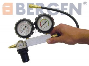
Available with either single gauge or twin gauge manifold. Gauge(s) show % of cylinder leakage or cylinder leakage and cylinder pressure. Suitable for use on any petrol engine with 14 or 18mm spark plugs.
2. SAFETY INSTRUCTIONS
- Ensure that Health & Safety, local authority and general workshop practice regulations are strictly adhered to when using tools.
- Maintain the equipment in good and clean condition for best and safest performance. DO NOT use if damaged.
- If required, ensure that the vehicle to be worked on is adequately supported with axle stands, ramps and chocks.
- WARNING! Select neutral (or ‘park’ if automatic transmission) and keep hands clear of the engine as engine rotation may occur when using this tool. The ignition MUST BE turned off.
- WARNING! Turn regulator knob fully anti-clockwise before connecting to compressed air.
- Excess pressure will damage the gauge and will invalidate the warranty.
- Wear approved eye protection. A full range of personal safety equipment is available from esellit.com.
- Wear suitable clothing to avoid snagging. Do not wear jewellery and tie back long hair.
- Account for all tools and parts being used and do not leave them in, on or near the engine.
- IMPORTANT: Refer to the vehicle manufacturer’s service instructions, or proprietary manual to establish the current procedure and data. These instructions are provided as a guide only.
- OVERVIEW. Once the leakage tester has been connected to one of the cylinders compressed air is fed into that particular cylinder through the built in pressure regulator. Diagnosis is made by observing the amount of leakage that is indicated on the cylinder leakage gauge and by listening for leakage at various points of the cars system.
3. AIR SUPPLY
The recommended hook-up is shown below.
- Ensure that the air valve regulator is in the “off” position before connecting to the air supply.
- You will require an air pressure of 45 to 100psi.
WARNING! Ensure the air supply is clean and does not exceed the pressure quoted. Too high an air pressure and/or unclean air will shorten the life of the tester due to excessive wear and may be dangerous, causing damage and/or personal injury.
- Drain the compressor air tank daily. Water in the air line will damage the tester.
- Clean compressor air inlet filter weekly.
- Line pressure should be increased to compensate for unusually long air hoses (over 8 metres). The minimum bore for hose and fittings is 1/4”.
- Keep hoses away from heat, oil and sharp edges. Check hoses for wear and make certain that all connections are secure.
4. INSTRUCTIONS
4.1 Location of listening points
- Oil Dipstick Tube – for leakage from damaged or worn rings and/or cylinder wall.
- Radiator FILLER – for cylinder wall cracks or head gasket leakage.
- Adjacent Cylinder – for head gasket leakage.
- Tail Pipe – for exhaust valve leakage.
- Carburettor Air Inlet – for inlet valve leakage.
- Fuel Injection Throttle Body – for inlet valve leakage.
4.2 Connecting the system
- Run the engine until it reaches operating temperature.
- Remove spark plugs, oil dipstick, radiator cap, air filter from carburetor or, if fuel injected, remove air filter or hose from the throttle body.
- Position No.1 piston at TDC on the compression stroke so that both inlet and exhaust valves are closed. Note: Always rotate the engine in the normal operating direction. To position the piston correctly use a piston position gauge and remove the cam/rocker cover so that closed valves can be confirmed.
- Screw the cylinder hose into the spark plug hole. If connecting to a 10 or 12mm thread, use adapters 9 or 10 as appropriate. Insert connector ‘A’ on the cylinder hose into connector ‘B’ on the tester hose.
- Screw a 1/4″BSPT male air line connector fitting into the threaded hole on the side of the regulator.
- Turn the regulator knob on the tester fully anti-clockwise to shut down the regulator before connecting the air. Connect the compressed air, which must be between 45 and 100psi, to the regulator. Turn the regulator knob clockwise slowly until the pressure gauge is showing about 60psi. Any leakage present will show on the cylinder leakage gauge as a percentage loss.
- Test all other cylinders, each at TDC, and compare the leakage figures to determine which cylinders are faulty.
- If necessary, retest the cylinder(s) showing high leakage. Check the listening points (see 4.1) to determine the cause of the leakage.
4.3 Helpful Suggestions.
- If 100% or excessive leakage shows on gauge the cylinder may not be at TDC on the compression stroke. Check to ensure that the valves are closed. Always try to position piston at TDC for uniform results.
- If rings are broken or cylinder walls are scored excessive leakage will be identified.
- It is important that all cylinders have reasonably uniform readings (as in compression testing). Differences in excess of 15% indicate excessive leakage.
- Large engines tend to leak more than small engines.
- If leak is excessive on a vehicle with low mileage, piston rings may be stuck. Treat engine with quality tune-up oil for a period of time and then re-test before disassembling.
- The lower the pitch of the leakage sound, the greater the leak.
- To assist with listening use a length of clean hose, or a mechanic’s stethoscope with the probe removed.
- When making repeat tests on the same cylinder, variations in the piston position and engine temperature can cause gauge readings to differ by up to 10%.
- If an engine has multiple faults (such as worn rings and burned valves), the tester may indicate only the most serious fault.
Note: There is always some leakage past the piston rings. As a result you will always hear some leakage when listening to the dipstick tube.
5. FAULT DIAGNOSIS
Compression condition
Action/diagnosis
Low compression reading on some cylinders.
(a) Use oil in cylinder to see if rings are worn.
(b) If compression increases, rings and/or cylinder wall are worn.
(c) If compression does not rise, do a cylinder leakage test to determine source of problem.
High relative compression readings and relatively equal cylinder readings.
But, if excessive exhaust emissions, lack of power, poor performance, or poor fuel consumption do a cylinder leakage test to determine source of problem.
Lower relative compression readings. One or more cylinders lower than others.
Do a cylinder leakage test to determine source of problem.
Author – Tony Heywood

Tony Heywood is a ‘Retail Troubleshooter’ with 40 years experience in the retail industry, specialising in e-commerce over the last decade. He has his own consultancy firm and is MD of ’e sell it’, an on-line store selling tools and auto-care products worldwide.
For tools & auto-care products at trade prices, please visit: www.esellit.com
Or call: 020 8201 0588